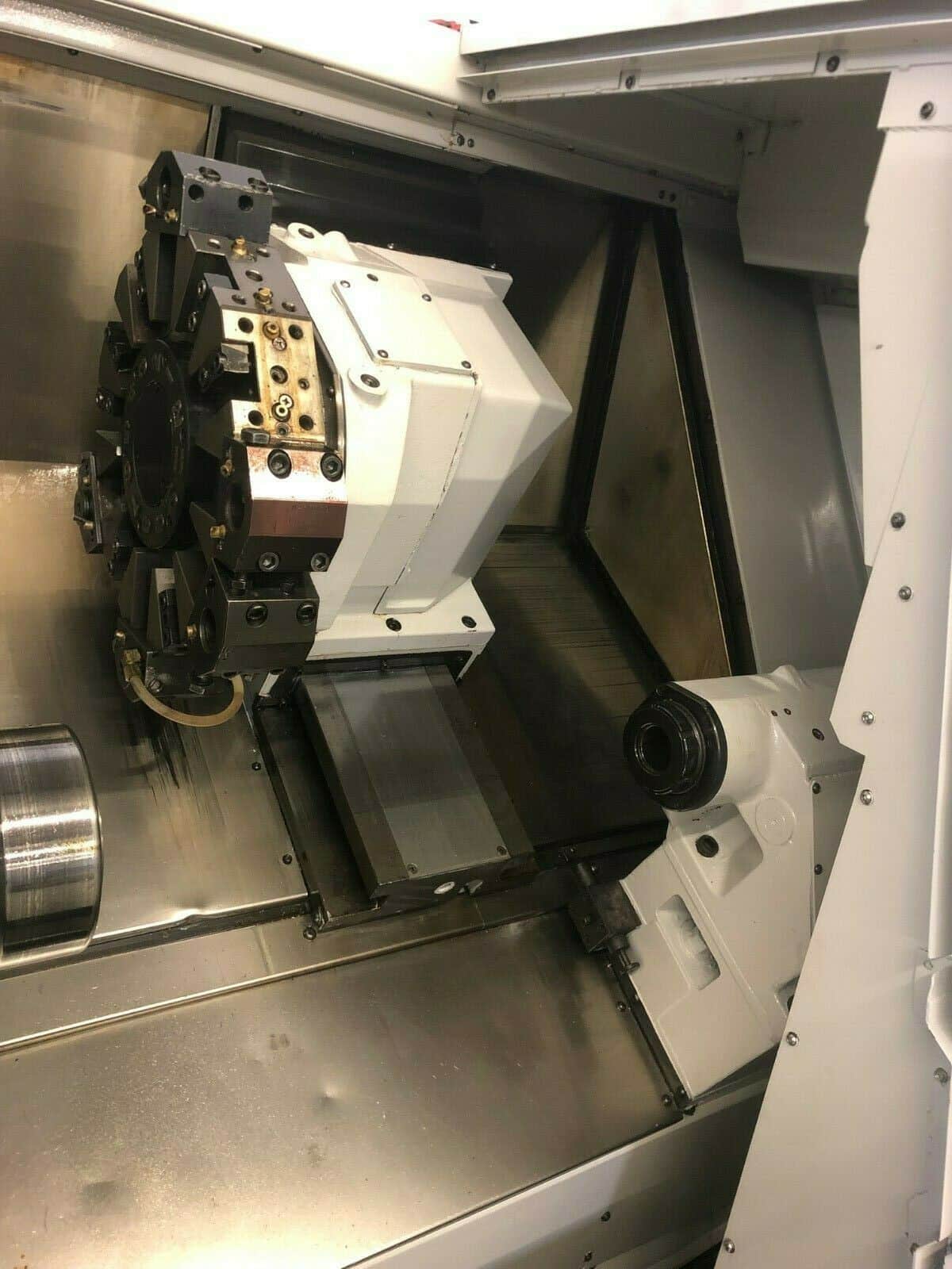
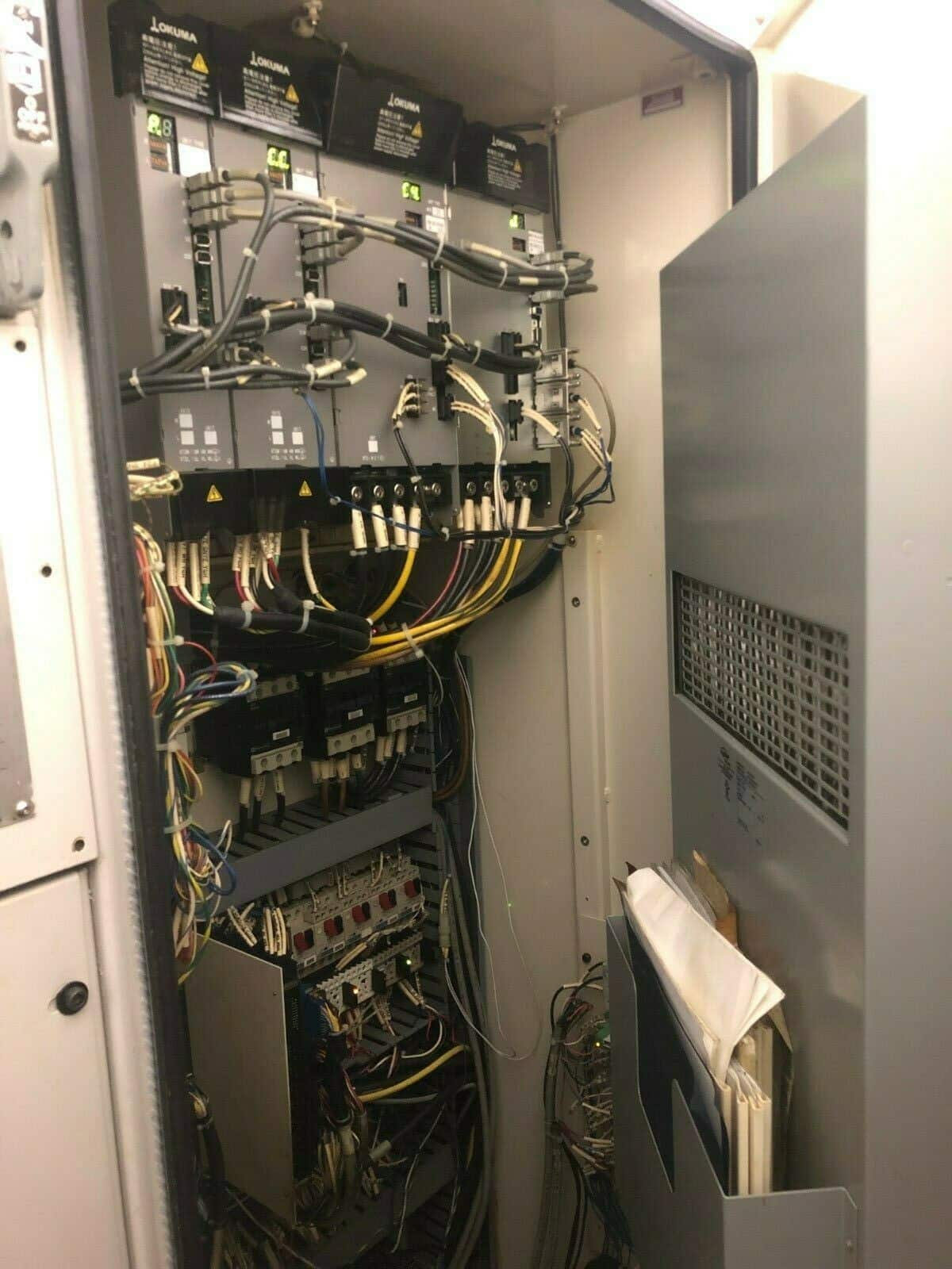
Okuma Lathe Captain L370m Parts Manual
Okuma Maintenance Manuals. Okuma ES-L6 Lathe Operation Maintenance Manual. Okuma LR15 OSP5000L-G Operation Maintenance Manual. Okuma VMC MC-4VA OSP5000M-G.
- Alberti Adjustable Angle Head VDI 40 for Okuma L370M and Similar ER25. OKUMA GENOS 2SP-150H MANUALS IN CD FORM:ZZCD194964 4 COPY MAKE OFFER. HYDRAULIC CHUCKING.
- Okuma Manuals Instruction Manual and User Guide for Okuma. We have 145 Okuma manuals for free PDF download. Lyndex-Nikken Okuma Live & Static Tooling Catalog capt 2013. OKUMA CNC 501 Programming Operation Lathe Manual. Okuma LC20 Lathes OSP 3000L Parts Book. Okuma ES-V 4020 OSP U10M Operational Maintenance Manual.
- Okuma CNC Lathe-Captain-L370 L-M-Parts Manual-290 pgs Okuma Gauging System OSP-P100L – Instruction Manual – 363 pgs Okuma Type LS High Speed Lathe – Operation Manual – 117 pgs Okuma MC-5H & MC-6H Horizontal Machining Center – Electrical Technical Manual – 38 pgs.

 BACK
BACKMachine Details
LIVE TOOLING / MILLING
NEW IN: 2001
SPECIFICATIONS:
Max Swing Over Bed................... 20.08'
Maximum Turning Diameter....... 13.38'
Maximum Turning Length.......... 20.47
Cross Travel (X-Axis)................... 10.23'
Longitudinal Travel (Z-Axis)....... 20.47'
Feed Range (Infinitely Variable)..... 1-400
Rapid Traverse Rate (X-Axis).......... 787 IPM
Rapid Traverse Rate (Y-Axis).......... 984 IPM
Number of Turrets...................... 1
Tool Positions............................. 12 All Live

Size Of OD Tool........................... VDI 40 1” square

Live Tool Power.......................... 9.4 HP
Spindle Bore................................ 2.44'
Spindle Nose............................... A2-6
Spindle Speed Range (1 RPM Increments)...... 38-3800 RPM
Spindle Horsepower............................ 20 HP
Approximate Machine Dimensions.... 87' x 68'
Approximate Machine Height............. 69'
Approximate Machine Weight............. 11,500 LBS
EQUIPED WITH:
Okuma E100L CNC Control
High Pressure Coolant (Chip Blaster)
RS-232 Port
Swing Down Toll Setter
320 meters Memory
HI G Control
Okuma Lathe Captain L370m Parts Manual Youtube
Tool Life Management
One Touch IGF
Chip Conveyor
8' 3-Jaw Kitagawa Chuck
Programmable Tailstock,
Auto Backlash Compensation
Complete Okuma Lathe G and M Codes list for cnc machinists who work on Okuma cnc lathe machines.
Contents
Okuma Lathe G Codes
| G Code | Description |
|---|---|
| G00 | Positioning |
| G01 | Linear Interpolation |
| G02 | Circular Interpolation (CW) |
| G03 | Circular Interpolation (CCW) |
| G04 | Dwell |
| G20 | Home Position Command |
| G21 | ATC Home Position Command |
| G22 | Torque skip command |
| G28 | Torque Limit command cancel |
| G29 | Torque Limit command |
| G30 | Skip cycle |
| G31 | Fixed thread cutting cycle: Longitudinal |
| G32 | Fixed thread cutting cycle: End Phase |
| G33 | Fixed thread cutting cycle |
| G34 | Variable lead thread cutting cycle: Increasing lead |
| G35 | Variable lead thread cutting cycle: Decreasing lead |
| G36 | Machine spindle-feed rod synchronized feeding (forward) |
| G37 | Machine spindle-feed rod synchronized feeding (reverse) |
| G40 | Tool Nose Radius Compensation: CANCEL |
| G41 | Tool Nose Radius Compensation: LEFT |
| G42 | Tool Nose Radius Compensation: RIGHT |
| G50 | Zero Offset. Maximum Spindle Speed Designation G62 Mirror image designation |
| G64 | Mirror image control OFF |
| G65 | Mirror image control ON |
| G71 | Compound Fixed Thread Cutting Cycle: Transverse |
| G72 | Compound Fixed Thread Cutting Cycle: Longitudinal |
| G73 | Longitudinal Grooving Compound Fixed Cycle |
| G74 | Transverse Grooving Compound Fixed Cycle |
| G75 | Automatic Chamfering |
| G76 | Automatic Rounding |
| G77 | Tapping compound fixed cycle |
| G78 | Tapping cycle reversed thread |
| G80 | End of Shape Designation (LAP) |
| G81 | Start of Longitudinal Shape Designation (LAP) |
| G82 | Start of Transverse Shape designation (LAP) |
| G83 | Start of Blank material shape definition (LAP) |
| G84 | Change of cutting conditions in bar turning cycle (LAP) |
| G85 | Call of Rough Bar Turning Cycle (LAP) |
| G86 | Call of Rough copy Turning Cycle (LAP) |
| G87 | Call Finish Turning Cycle (LAP) |
| G88 | Call of continuous thread cutting cycle (LAP) |
| G90 | Absolute Programming |
| G91 | Incremental Programming |
| G94 | Feed Per Minute Mode (MM.MIN) |
| G95 | Feed Per Revolution Mode (MM/REV) |
| G96 | Constant Cutting Speed “ON” |
| G97 | Constant Cutting Speed “OFF” |
| G101 | Linear Interpolation in Contour Generation |
| G102 | Circular Interpolation in Contour Generation (FACE) (CW) M |
| G103 | Circular Interpolation in Contour Generation (FACE) (CCW) |
| G110 | Constant speed cutting on turret A |
| G112 | Circular thread cutting CW |
| G113 | Circular thread cutting CCW |
| G132 | Circular Interpolation in Contour Generation (SIDE) (CW) |
| G133 | Circular Interpolation in Contour Generation (SIDE) (CCW) |
| G136 | End of Coordinate System Conversion or Y-Axis Mode OFF |
| G137 | Start of Coordinate System Conversion or Y-Axis Mode OFF |
| G140 | Designation of Machining Mode Using Main Spindle |
| G141 | Designation of Machining Mode Using Sub Spindle |
| G161-G170 | G-code macro function MODIN |
| G171 | G-code macro function CALL |
| G178 | Synchronized tapping cycle (forward) |
| G179 | Synchronized tapping cycle (reverse) |
| G180 | Machine Compound Fixed Cycle: CANCEL |
| G181 | Machine Compound Fixed Cycle: DRILLING |
| G182 | Machine Compound Fixed Cycle: BORING |
| G183 | Machine Compound Fixed Cycle: DEEP HOLE DRILLING |
| G184 | Machine Compound Fixed Cycle: TAPPING |
| G185 | Machine Compound Fixed Cycle: LONGITUDINAL THREAD CUTTING |
| G186 | Machine Compound Fixed Cycle: END FACE THREAD CUTTING |
| G187 | Machine Compound Fixed Cycle: LONGITUDINAL STRAIGHT THREAD CUTTING |
| G188 | Machine Compound Fixed Cycle: TRANSVERSE STRAIGHT THREAD CUTTING |
| G189 | Machine Compound Fixed Cycle: REAMING/BORING |
| G190 | Machine Compound Fixed Cycle: KEYWAY CUTTING CYCLE |
| G191 | Machine Compound Fixed Cycle: LONGITUDINAL KEYWAY CUTTING CYCLE |
Okuma Lathe Captain L370m Parts Manual Download
Okuma Lathe M Codes
| M Code | Description |
|---|---|
| M00 | Program Stop |
| M01 | Optional Stop |
| M02 | End of Program |
| M03 | Spindle CW |
| M04 | Spindle CCW |
| M05 | Spindle Stop |
| M06 | Tool Change |
| M08 | Coolant ON |
| M09 | Coolant OFF |
| M12 | Machine Spindle STOP |
| M13 | Machine Spindle CW |
| M14 | Machine Spindle CCW |
| M15 | C-Axis Positioning |
| M16 | C-Axis Positioning (NEG) |
| M17 | CEJ MATIC :Request of Data transfer |
| M18 | Post-process Gauging RS232C: Request of Data transfer |
| M19 | Oriented Spindle Stop |
| M20 | Tailstock Barrier OFF or spindle interference monitoring OFF (opposed two-spindle models) |
| M21 | Tailstock Barrier ON or spindle interference monitoring ON (opposed two-spindle models) |
| M22 | Chamfer OFF |
| M23 | Chamfer ON |
| M24 | Chuck Barrier OFF, Tool interference OFF |
| M25 | Chuck Barrier ON, Tool interference ON |
| M26 | Thread Lead Along Z-Axis |
| M27 | Thread Lead Along X-Axis |
| M28 | Tool Interference Check Function OFF |
| M29 | Tool Interference Check Function ON |
| M30 | End of Program |
| M32 | Straight In-feed along thread face mode (on left face) |
| M33 | Zigzag in feed in Thread Cutting |
| M34 | Straight In-feed along thread face mode (on right face) |
| M40 | Spindle gear Range Neutral |
| M41 | Spindle Gear Range 1 |
| M42 | Spindle Gear Range 2 |
| M48 | Spindle Speed Override Ignore Cancel |
| M49 | Spindle Speed Override Ignore |
| M55 | Tailstock Spindle Retract |
| M56 | Tailstock Spindle Advanced |
| M58 | Chucking Pressure Low |
| M59 | Chucking Pressure High |
| M72 | ATC Unit Position at Approach Position |
| M73 | Thread Cutting Pattern 1 |
| M74 | Thread Cutting Pattern 2 |
| M75 | Thread Cutting Pattern 3 |
| M76 | Parts Catcher Retract |
| M77 | Parts Catcher Advanced |
| M78 | Steady Rest Unclamp |
| M79 | Steady Rest Clamp |
| M80 | over cut Advanced |
| M81 | over cut Retract |
| M83 | Chuck Clamp |
| M84 | Chuck Unclamp |
| M85 | No Return to the Cutting Starting Point after the completion of rough turning cycle (LAP) |
| M86 | Turret Indexing direction: CW (reverse) |
| M87 | Cancel of M86 |
| M98 | Tailstock Spindle Thrust Low |
| M99 | Tailstock Spindle Thrust High |
| M109 | Cancel of M110 |
| M110 | C-Axis Joint |
| M134 | Z-Axis Thrust Monitoring OFF |
| M135 | Z-Axis Thrust Monitoring ON |
| M136 | Designation of Multiple fixed cycle configuration |
| M137 | Touch setter interlock release ON |
| M138 | Touch setter interlock release OFF |
| M139 | Lead Machining Function – Learning Operation |
| M140 | Tapping Cycle M-Tool Constant Rotation Answer Ignored |
| M141 | C-Axis Clamp or not Selection |
| M142 | Coolant Pressure Low |
| M143 | Coolant Pressure High |
| M146 | C-Axis Unclamp |
| M147 | C-Axis Clamp |
| M152 | M-Tools Spindle Interlock ON |
| M153 | M-Tools Spindle Interlock OFF |
| M161 | Feedrate Override Fix (100%) |
| M162 | Cancel of M163 |
| M163 | M-Tools Spindle Speed Override Fix (100%) |
| M168 | Ignoring M-Tool Spindle Constant Speed Answer |
| M169 | C-Axis NoClamp |
| M191 | M-Tool Spindle Orientation Direction Specified CW |
| M192 | M-Tool Spindle Orientation Direction Specified CCW |
| M197 | Thread Cutting Phasing Stroke Clear |
| M211 | Keyway Cutting Style: Minus Direction |
| M212 | Keyway Cutting Style: Zigzag |
| M213 | Keyway Cutting Style: Designated Depth Infeed |
| M214 | Keyway Cutting Style: Equal Depth Infeed |
